Physical Dimensions
Myriad cards use the M.2 form factor, also known as “NGFF”. It is commonly used by NVMe SSDs and Wifi cards. This means that the M.2 specification serves as the basis for the Myriad specification.
This page describes the physical dimensions required to create a Myriad-compatible card. You can also use one of our footprints if you want to save yourself some trouble.
Make sure you order your cards with a thickness of 0.80mm!
Keying
Myriad cards, like all other M.2 cards, have a physical “notch” preventing the insertion of incompatible cards. Myriad cards use Key A. This means pins 8-15 are missing. Pins 24-31 (Key E) are kept reserved for potential future use.
Card edge
In order to allow insertion, the card must be 0.80mm (± 0.08mm) thick. ENIG finish is strongly recommended for durability. Contrary to the M.2 specification, a card edge bevel is not required.
For card edge pads and cutout dimensions, please see Figure 16 through 18 of the M.2 specification (pages 39-41). We recommend using our pre-existing footprints to avoid having to manually copy this.
Card dimensions
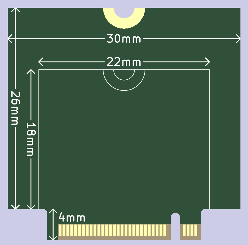
We define a set of standard card sizes to make it easier to determine whether a card will fit a specific keyboard.
The following sizes are defined:
| Size codes | 22mm wide | 30mm wide | > 30mm wide |
| 22mm tall | SS | SM | SL |
| 30mm tall | MS | MM | ML |
| > 30mm tall | LS | LM | LL |
Cards which are Small or Medium in either width or height will always fit into a keyboard matching that size. Cards which have one or more Large dimensions are not guaranteed to fit - the card maker should publish exact dimensions and compatibility with the most common keyboards.
If physically possible, the size code should be marked LINK on the card itself.
Card height includes the 4mm needed for the connector.
Standoff
The card is secured using a standoff and regular M2.5 screw. If the keyboard supports cards of length S (22mm) or larger, a standoff will be present at 22mm. If the keyboard supports cards of length M (30mm) or larger, a second standoff will be present at 30mm.
The card must have a circular cutout at either y=22mm or y=30mm with a diameter of 2.7mm (radius 1.35mm), surrounded by a plated pad with a diameter of 5.4mm (radius 2.7mm). On most cards, this will result in a half-circle due to the card’s length.
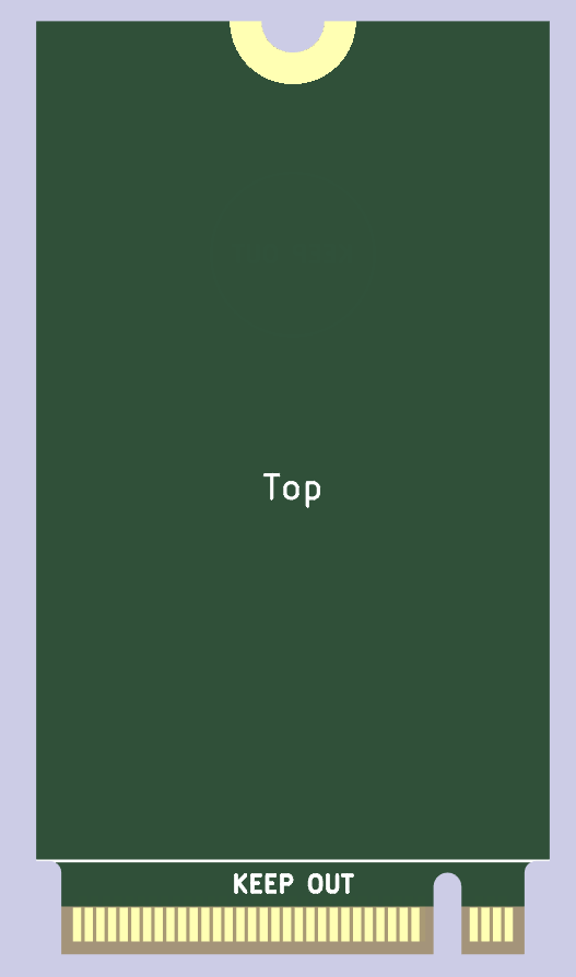
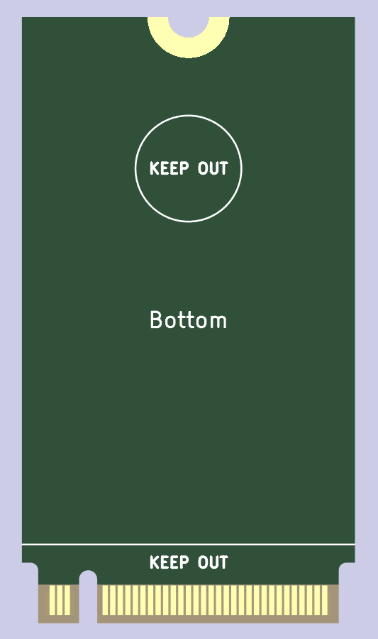
Keepout areas
In order to avoid interfering with the socket, do not place any components:
- Within 4.0mm of the connector card edge on the frontside.
- Within 5.2mm of the connector card edge on the backside.
Within a 3.5mm radius of (x=0mm, y=30mm) on the backside, do not place any components n order to avoid interfering with the 30mm standoff. Placing signal or power traces in this area is strongly discouraged, but a ground plane is fine.
Vertical spacing
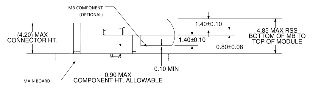
Components on the bottom of the cards must be at most 1.40mm tall, leaving 0.90mm for components placed on the keyboard. Component height on the top is unrestricted, provided they remain within the card boundaries.
Keyboards may use connectors shorter than 4.20mm - but that makes finding standoffs a lot trickier.
Mounting Hardware
If you are designing your own keyboard, we recommend the TE Connectivity 2199230-8 (datasheet) connector and Wurth Elektronik 9774025151R (datasheet) standoffs, but any compatible ones will do.
Footprints are provided in our repository.